5 September 2024
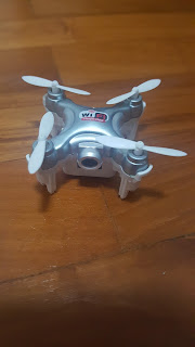
I have not flown the ZY-320 (2 channel 2-motor plane of 210mm wingspan) but I toyed with it. After the model is initiated and is bounded to the transmitter, tilting one wing low causes a change in the spinning noise of the twin motors. This means it has a gyro to keep the wings level. The twin motors were 0714, driving 45mm pusher propellers and the cell is 150mah. The whole model is described as 25grammes. The cell is inserted from the rear, the motors are protected with skids in the motor mount and there are 2 very small wheels about 15mm diameter. ROG may be possible with this model.
If I were to use the airborne parts with minimum modifications and keeping the wheels and using the twin skids, I will need to make a beam mount for the twin motors, thus creating a sort of power pod and command centre. The easiest and laziest way to mount this pod is below the model. What are the effect of a low CG and low thrustline?
There will be inherent pendulum stability, doing away with dihedral at the model. The wheels and skids allow sliding landing on smooth ground. If model has no yaw stability, the pod can have fin or fins. The pod can have horizontal stabiliser for pitching stability. The thrustline is below the centre of drag/lift, may need up thrust.
How about a parasail, an autogyro, a kite, a bird, a disc/square/oval or even a Doraemon?
23 August 2024
I just placed my order to AliExpress for a 2 channel 2-motor plane of 210mm wingspan. I think it'll fly indoors and it costs less than $20. Better to pay this then figuring out limitations and hacks to a CX-10.
I'll fly the model a few times to see if I like it.
If I do, I'll figure out how to get more 150mah batteries.
If I don't like it, it's $20.
If the model is all battered or I got bored flying it, I'll break out the parts and do my own model!
To convert a twin-counter-rotating-motor pusher plane to a twin-counter-rotating motor pulling plane, the motors will stay on the side they were, but remember to pull out and swap the propellers.
The $20 model's board has some kind of stabilisation because the model does not have any dihedral. If it works out well, it can mean I am not restricted to modelling high wings. I am also not restricted to 2 engined planes, 3 or 4 engined would also work out well. And must it have propeller? Well, the <$20 model is supposedly a jet plane.
I wonder what is the weight of the airborne pack. I have chosen the smaller model that flies with 150 mah cell.
It is such a tiny model, but it is a SU or something so I would work out the entire model's horizontal area (fuselage, wing, tail) and not consider the 210mm wingspan. Just make the new model bigger for slower flight, bigger in terms of the aforesaid horizontal area.
21 August 2024
Aliexpress still have Cheerson CX-10. CX-10 has the 1s mah battery inside the main body and exposes only the charging port. Extra batteries are available, with or without plugs and some are bundled with charger and charging adapter cables.
4 October 2016
This is the Eachine E010, only available as Mode 2.
I like the four bladed propellers in the protector rings and the rings are duct design with a good lip for better draw.
The vertical lift seems more powerful than the CX10A (and of course more than the WD-TX which is heavier). It could be because of different motor speed control setting but perhaps not.
If I want, I can connect the ducted fans to WLToys receiver board and make an RC jet.: Boeing, Airbus or even the A-10? Many possibilities.
18 August 2016
Not a plane but I bought another CX10A and a CX-10WD-TX.
The latter is WiFi controlled, comes with a transmitter and it is a FPV drone that can take photos and videos. It also have height hold, one touch take off and one touch landing. I bought it from Rotor, listed price 69SGD.
7 June 2016

Ooh, a Bl
ériot 115 or 155 is also possible and it seems they are easier to do than a HP42.
The 155 had the same 4 engine configuration but there's no 'inverted gull' kink to the lower wing and the engines were mounted clearly on top of the wings.
There's one door and it was at the nose!
The 155 was smooth skin, no corrugated steel sheets.
Easy radiators to do.
Both upper and lower wings were of equal span, so I don't have to measure the spans of the model.
It had interesting names, in this one, it was called 'Clement Ader'.
Single tail, unlike the boxed tail of the HP42.
This was the 115.
It seems it had a front viewing windows for the passengers.
Don't know if the access for passengers were from the nose. But pity the pilots/navigator, sitting exposed.
Which motor should connect to which arm of the quad controller and which direction should that motor turn? This is what I came up with, but there's something wrong with it.

This configuration would work, but aileron input yaws the plane and rudder input rolls the plane. I haven't stumble on the correct configuration yet.
It's not just the inputs I am concerned about, it's how the quad controller will stabilise the model. When the quad controller detects a roll, translated, the low side speeds up when I'd rather have it speed up opposing motors that give a yaw, which is a roll...see? See? I can confuse easily by writing too much, no wonder I didn't get what I wanted.

So, here's the final configuration which I think is correct.
When I want to roll to the right, quad arms 1 and 3 gives more voltage, the opposing pair of motors at 1.30 and 7.30 speeds up and the torque rolls the model right.
When I want to yaw to the right, quad arms 2 and 3 (I have to verify this) gives more voltage to the motors at 1.30 and 4.30, which speeds up and yaws the model towards the right.
When I want to pitch up, quad arms 1 and 2 gives more voltage to motors at 4.30 and 7.30 and the model pitches up.
16 May 2016
This Eachine H8 mini was delivered last week. I bought it from Banggood because it is cheaper than the Cheerson CX10A, have bigger motors, propellers and the battery connection uses the white plugs.
I bought a Mode 1 type but the aileron and rudder are on the wrong sticks. It is actually a Mode 3 transmitter.
It flies ok, quieter than the CX10A, but it took conscious effort to adapt to Mode 3. So I could hover but not much more.
The propellers are bigger than CX10A's but smaller than the Hubsans which I had bought a few for experimentation. The motors spins free but that is probably because of the increased mass of the propellers?
The plastic frame is flexible and does not break. The guard rails looks ok but are not as useful as a cage because they are too small and do not form a protection ring.
28 April 2016
I am not sure if my visualising of movements is correct.
Question:
If the motors and propellers are forward facing but the board is mounted horizontally, the throttle, ailerons and elevator direction is the same, but what is the effect on the rudder, i.e. vertical axis?
There are two things to consider: the self-stabilising horizontal rotation about the vertical axis and the stick inputs.
Arguments:
When there is a deviation, for example, the quad board were to be displaced in a clockwise rotation (in a vertical axis, i.e. turning right), the two pairs of motors placed horizontally forward facing will react to compensate by rotating about the horizontal axis in an anticlockwise rotation (the model will bank right). This is contrary to the desired banking direction as what we want is for the model to bank left for left turn.
When the rudder stick is pushed to right, we want the model to bank right but the horizontally aligned motors will cause the board/model to bank left. This is also contrary to the desired banking direction because wheat we want is for the model to bank right for right turn.
Solution:
I think I can get the desired rudder stabilising and output by swapping the two pairs of motors, for example for the front-left motor, which translates to bottom-left, it shall be changed from clockwise rotation to one which has anticlockwise rotation.
Front view:
CA to AC
AC to CA
5 April 2016
Last night I decided to open up the CX10A. I didn't want to but I had to. It's either out with the soldering gun or out with the CX10A; there's no point keeping toys you can't play with. Forego the idea that one day it can be salvaged as parts for a new toy, life is too short.

First I pinched the 4 propellers out of the motor shafts. Then I took out the 4 screws and carefully plied open the latches which are molded to the white plastic bottom cover piece. Gingerly the top cover was removed and the PCB pried out.
Can't see really, but with the camera phone to the rescue, all becomes clear where the wire was disconnected. I tried to see if the solder will met the plastic sleeve, so I don't have to strip the wire: nope. I tried to strip the wire with a pair scissors and cut it instead. I tried again but was really gentle this time and managed to bare a fresh wire core. I tinned the bared wire, or at least I think I did. All this time I can't see what I was doing and it was by 'feel'. Whether the wire is tinned or not I do not know. All I know is that I tried. The soldering part was completed by 'feel' too. I tugged the wire and it seems to hold. The CX10A was re-assembled and it worked. I then discovered there's this small square transparent plastic piece. I suppose that is to be inserted between the battery and the PCB. It worked for a couple of flights until I crashed it and the same motor stopped working.
I hadn't stored away my soldering gear yet, so I disassembled the CX10A, performed the soldering again (this time I didn't bare a new length or tinned the exposed end), assembled the CX10A and it is working. This time, it was much easier, experience equals familiarity? I didn't fit the small square transparent plastic piece, I wanted to but didn't find it (later on, I stored the plastic piece in the battery compartment of the transmitter.
I think that during a crash, the contact point broke off when that motor twisted. So I thought of hotgluing the motor to the bottom cover, knowing though, that that would mean that I will have some difficulties if I have to disassemble the CX10A again. I thought of superglue, UHU and then settled on a particular glue paste that came in a tube. This glue says it is all-purpose, it looks to be some form of paste compound which won't dissolve in water when dried. I remembered that the paste dried hard.
I applied a bit of it on the exposed sides of the motors after assembly. Then I decided to installed the cage (it has snapped in a few places, but should still be ok) and applied more glue to the bottom of the motors. Only time will tell, but I think this is a good move.
My CX10A flies only a bit longer than 3 minutes and the battery was hot to touch.
1 April 2016
It is the end! Banggood does not ship their lipos to Singapore, no matter how small!
I bought another CX10A and was having a good time until one motor stopped reacting. Perhaps it is a simple matter of opening up and re-soldering, but what shall I do if it is not. Meantime I bought another mini/nano Quad: Eachine H8 Mini Headless Mode 2.4G 4CH 6 Axis RC Quadcopter RTF, for $18.50. It looks to be larger and the lipo is 150mah with the white plug.
I also bought 10x of the male and female white plugs. They would come in useful one day.
30 September 2015
I printed this drawing on A3 for study. The Cheerson propeller fits inside the prop arc and the motor fits in the nacelles too.
A wing jig is required to have the wings assembled correctly because the top and bottom wings are polyhedral and the struts are numerous and requires careful alignment.
Prepare jig and slot in long strips of PVC to form the warren-truss for both front and back struts.
The struts between the top motors and the bottom motors to be made rigid. Glue CF rods to these four struts (front and back).
Prepare and finish the wings, checking dihedral breaks with jig.
Solder magnet wires to motors and glue motors onto wings.
Assemble and glue the jigged struts onto the lower wings and then the upper wings.
Remove jig and leave the glued in struts in placed. The jig would be destroyed in the process.
Cover motor with paper nacelles.
Glue on the diagonal struts.
Tidy up the motor wires. Solder motor wires to board.
Place and glue the biplane onto the finished fuselage.
Run the motor wires to the fuselage.
Cover fuselage and wing joints with paper.
Glue the board to nose.
Make hatch to access board. To switch on and to charge.
Glue the tail and landing gear to the fuselage.
 |
| The 4 arms (and SM LEDs) would protrude pass the fuselage's outline. The propeller fits in the propeller arc described. |
 |
| Overview. |
 |
| Comparison with 20" Kirby Cadet. |
 |
| Perhaps 15" wingspan? |
 |
| The motor would fit nicely in the nacelle's outline and the propeller is just about the right size. There seems to be no space for detailing the Bristol Jupiter engine. |
28 September 2015

I took the Cheerson CX10A out yesterday and couldn't get it to bind. I charged the quad and the USB charging was lighted for a very long time. I picked it up and felt that the 1s cell is very hot.
I haven't been flying the Cheerson CX10A for a few months (maybe 6 months). I think the lipo was damaged by the deep discharge. I could buy a replacement cell from Banggood and replaced the damaged battery but I don't think it is worth my effort. I didn't enjoy flying it. I suppose the board and motors are ok from the last flight many months ago, so I thought how I could re-use and modify it to airplane use.

First to mind was a 4-propellers biplane. Preferably with 2 motors at the top pair of wings and 2 at the bottom. I scour the internet and found the Handley Page HP 42.
With this arrangement of 4 motors, I could place the board in a horizontal position. So long I make this model of HP 42 to be free flight capable, there should not be any reason that I can't control the flight direction when the board and motors are working. Infact, I would have auto-stabilisation which makes flying even easier.
When the model is banked, the 2 motors on the inside pair of wings would spin faster and the opposing twins slower. When diving, the 2 motors on the lower pair of wings would spin faster and the upper pair slower. This would keep the model in a level attitude and pushing the throttle up will have the model fly faster and higher.
The model could be built from simple foam and paper and I could extend the motors' leads by using magnetic wires instead since I have ordered some from Banggood.

The CX10A weighed 12.0gm. I suppose a Handley Page HP42 under 20gm is possible since there is no other airborne electronics to add.

I opened up my CX10A and noticed I don't have the antennae like in the CX10, maybe the antennae is printed on the board. As it works, I am not bothered.
Here's the top view. The charging socket is at the top and the switch is under the board.


A study of the connections of the batteries and motors. Positive: White, Red. Negative: Black, Blue

I like minimal intervention and work; I don't like wasting. So I thought of how I could make full use of the switch and charging socket. While it is a simple matter to solder battery connectors and use that as a switch and charging socket, just because I like to do minimal work, I think it might equally be easy if the battery and board are in one unit, like the way it came in, and provide recess instead to have access at the built-in switch and charging socket.
The placement of the board could simply be atop the upper wings of the HP 42 for easy access or I could do some other model with the board tucked in somewhere less conspicouous and even have the small LED shining bright. And this gave me this idea. A X-Wing Fighter.
Have the motors either in tractor or pusher mode.
Have the board glued underneath the fuselage.
Have thin transparent pvc foreplanes if necessary.
Maybe the foreplanes won't be necessary because of the mems gyro onboard.
Whatever it is, the most important thing for success is that the model must be able to glide.


